
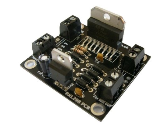
UpSmart PCBA supports OEM & EMS, PCBA for Robotics, dual H-bridge motor driver PCBA, L298N motor controller board assembly, DC motor drive PCBA for robotics, smart car motor driver PCB, industrial robot motion control PCBA, stepper motor driver module assembly, robotics power electronics PCBA, IPC Class 2 robot controller board, embedded motor drive PCB manufacturing, mobile robot motor control PCBA
If you’ve ever scaled a mobile robotics project from bench prototype to production, you already know the hard truth: PCBA for robotics is not just a microcontroller plus a few power components wired together. A motor drive board that works perfectly on a benchtop power supply will often overheat, throw encoder noise, or fail outright once installed in a real robot—because power-loop inductance, thermal dissipation, ground bounce, and electrical noise are all invisible on a schematic. They all punish design shortcuts the moment you run a motor under real load.
This deep dive breaks down a production-ready dual H-bridge DC motor driver PCBA built around the ST L298N platform, from a manufacturing engineering and procurement perspective. We’ll cover power architecture, layout decisions that directly impact reliability, volume production quality gates, performance grade selection, and how to vet an EMS partner that delivers consistent, field-proven drive boards — not just units that pass a no-load bench test. No generic marketing claims — just the technical and operational details that determine your field failure rate, motion accuracy, and total program cost.
This assembly is a general-purpose dual-channel motor drive module designed for mobile robots, automated guided vehicles, educational robotics platforms, and stepper motor control systems. It uses the industry-standard L298N monolithic H-bridge IC to deliver controlled power to inductive motor loads, with built-in protection and field-wirable terminal blocks for fast integration.
| Category | Specification | Design Rationale |
| Main Driver IC | STMicroelectronics L298N dual full-bridge driver | Industry-proven silicon for brushed DC and bipolar stepper motor control; through-hole package for thermal performance and serviceability |
| Output Configuration | 2x independent H-bridge channels | Drives two DC motors (forward / reverse / PWM speed control) or one 4-wire bipolar stepper motor |
| Input Voltage Range | 46 V DC | Compatible with standard 12V and 24V mobile robot battery systems |
| Continuous Output Current | 4 A per channel | Rated for sustained operation; peak current supported for short acceleration events |
| Protection Features | Over-temperature shutdown, over-current protection, freewheeling diode network | Full fault protection for both driver IC and connected motor loads |
| Control Interface | Logic-level enable / direction / PWM inputs | 3.3V / 5V compatible; works with all common robotics MCUs and motion controllers |
| PCB Construction | 2-layer FR-4, 2 oz copper on power paths, lead-free HASL | Heavy copper for low-resistance power paths; through-hole power components for mechanical stability |
| Mechanical Features | 4x mounting holes, screw-terminal I/O | Vibration-resistant installation; tool-free field wiring for robot assembly and service |
| Workmanship Standard | IPC-A-610 Class 2 | Standard for industrial and educational robotics; Class 3 available for high-reliability deployments |
The through-hole construction for the main power IC and terminals is a deliberate choice for L298N motor controller board assembly in robotic applications. Surface-mount equivalents save space, but through-hole packages deliver better thermal conduction to the board and far higher mechanical robustness under constant vibration — two non-negotiables for mobile robot platforms.
Three layout and design choices directly determine long-term reliability, and they are the most commonly skipped optimizations on low-cost commodity driver boards.
The high-current motor paths are routed as short, wide, balanced copper pours, with the freewheeling diodes placed as close to the output terminals as physically possible. This reduces switching spike voltage and parasitic inductance, which are the two leading causes of unexpected driver IC failure under load. For DC motor drive PCBA for robotics, even a few extra millimeters of power trace length can increase peak voltage spikes enough to destroy the driver chip during hard braking events. Cheap commodity boards ignore this detail, and they fail consistently in real robot deployments.
The L298N die is placed to allow direct heatsink mounting, with exposed copper pad area under the package to spread heat into the board. Power dissipation components are spaced evenly to avoid hot-spot stacking, and high-current traces use 2 oz copper to resist I²R heating. This is a critical detail for industrial robot motion control PCBA platforms that run for hours at a time — thermal drift does not just shorten part life; it changes switching behavior and degrades motion accuracy over time.
Logic-level control signals and power motor returns use a single-point ground connection, eliminating ground bounce and common-mode noise that would otherwise disrupt encoder readings and control signals. Anyone who has debugged a robot that loses position accuracy every time the motors run knows this problem. For stepper motor driver module assembly and closed-loop motion systems, clean signal isolation is the difference between consistent positioning and random step loss.
Consistent volume production of motor drive boards requires defined process gates that go far beyond basic SMT assembly. A mature robotics power electronics PCBA workflow includes these mandatory steps:
For mobile robot motor control PCBA programs, loaded burn-in testing is the step that most inexperienced EMS partners skip — and the step that catches 80% of field failures before units leave the factory.
Not every robotics program needs aerospace-grade drivers. Choosing the right performance grade is one of the highest cost and reliability decisions a procurement team makes.
| Grade | Typical Application | Continuous Current | MTBF Target | Relative Cost | Best For |
| Hobby / Educational | STEM robots, smart car projects, low-duty-cycle builds | 2 A | ~5,000 hours | 1.0x baseline | Classroom kits, entry-level robotics, low-cycle use |
| Industrial Mobile Robot | AGVs, warehouse robots, industrial automation | 3 A | > 50,000 hours | 1.8 – 2.2x | Commercial service robots, industrial material handling |
| High-Reliability Servo | Medical robots, aerospace, safety-critical motion | 4 A | > 100,000 hours | 3.5 – 5.0x | Safety-critical motion, long-service-life platforms |
Most commercial robotics programs fall into the industrial grade. Full high-reliability grade is only justified for safety-critical or long-service-life deployments where downtime cost is extremely high.
Robotics PCBA refers to printed circuit board assemblies purpose-built for robotic motion control, sensing, and power systems. These assemblies are designed for higher current, vibration resistance, thermal stability, and electrical noise immunity that standard consumer PCBAs do not require.
Most failures trace back to three design shortcuts: undersized power traces, inadequate freewheeling protection, and poor grounding that allows motor noise to disrupt control logic. All three are invisible on a schematic and only appear under real load conditions.
Technically, yes, but reliability varies dramatically. Power electronics require specialized stencil design, soldering profiles, and load testing that most general-purpose assembly lines do not maintain as standard practice.
Thermal overstress from poor copper sizing and missing heat path design is the number one failure cause. The second most common is switching spike damage from long, high-inductance power loops. Both are fully preventable with proper layout.
For production volumes above a few hundred units, burn-in almost always pays for itself in reduced field returns and warranty cost. It is especially valuable for motor drives, where early-life power component failures are common but easy to screen out.
If you’re developing a mobile robot, motion control platform, or educational robotics product and need a manufacturing partner with real power electronics and motion control experience, send us your design files, BOM, and target volume. Our engineering team will provide a complimentary DFM review, risk assessment, and transparent quotation with clearly separated NRE and per-unit costs.
We specialize in high-volume PCBA for robotics, including motor drivers, sensor interfaces, and motion controller boards, with controlled manufacturing processes, full traceability, and built-in thermal and reliability design support. Contact us today to discuss your program.
UpSmart PCBA brings nearly a decade of expertise to multilayer PCB manufacturing, serving industrial clients worldwide that demand tight tolerances, long-term durability, and batch-to-batch consistency.
We focus on custom PCB fabrication and full turnkey PCBA assembly. Your design files move straight through production into fully built, tested units ready for final installation — no fragmented handoffs between separate vendors. We scale seamlessly from small prototype runs to high-volume mass production, with end-to-end in-house capabilities spanning component sourcing, bare board manufacturing, in-process quality testing, and final packaging.
We build every order around three non-negotiables: quality, engineering rigor, and reliable turnaround. For our global industrial customers, this translates to simpler supply chains, fewer production disruptions, and electronic systems that deliver consistent performance over their full service life.
Email: sales@upsmartpcba.com
WhatsApp/Phone: +86 199 2656 6516
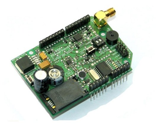
UpSmart PCBA supports OEM & EMS, PCBA for IoT, GSM GPRS IoT module PCBA, industrial IoT gateway board assembly, cellular IoT terminal PCBA, low power IoT device PCB, battery powered IoT sensor node assembly, IoT connectivity module PCBA service, embedded IoT control board manufacturing, wireless IoT communication PCBA, SIM based IoT device assembly, industrial grade IoT electronics PCBA
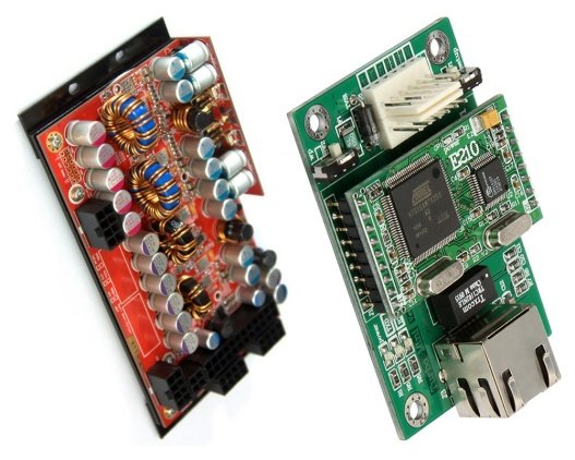
UpSmart PCBA supports OEM & EMS, PCBA for Power Supply, multi-channel DC-DC converter PCBA, industrial power supply board assembly, high current power module manufacturing, regulated power supply PCB service, switch mode power supply PCBA, power electronics contract manufacturing, IPC Class 2 power supply assembly, custom power converter board EMS, isolated power supply PCBA design, power supply unit (PSU) PCBA service
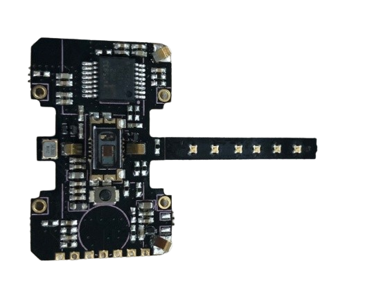
UpSmart PCBA supports OEM & EMS, PCBA for Wearables, wearable health tracker PCBA assembly, flexible PCB for smart wristband, Bluetooth low energy wearable module, biometric sensor PCB for wearables, 9-axis motion tracking PCBA, miniature wearable electronics manufacturing, low power wearable device PCB, smart bracelet PCBA service, IPC Class 2 wearable assembly, skin contact wearable PCBA design
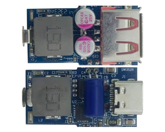
UpSmart PCBA supports OEM & EMS, PCBA for Automotive, automotive USB charger PCBA assembly, car charger PCB manufacturing, AEC-Q compliant PCBA for automotive, 12V to USB fast charger board, vehicle power adapter PCBA service, automotive electronics contract manufacturing, DC-DC converter PCBA for cars, IPC Class 2 automotive PCBA, aftermarket car charger PCB assembly, automotive power supply PCBA solution
specializing in end-to-end printed circuit board fabrication and full-turnkey PCB assembly services.