
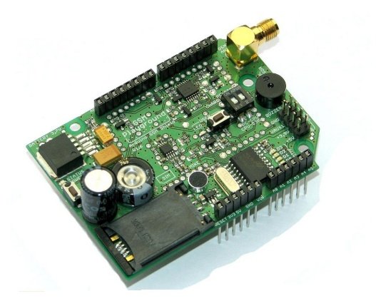
UpSmart PCBA supports OEM & EMS, PCBA for IoT, GSM GPRS IoT module PCBA, industrial IoT gateway board assembly, cellular IoT terminal PCBA, low power IoT device PCB, battery powered IoT sensor node assembly, IoT connectivity module PCBA service, embedded IoT control board manufacturing, wireless IoT communication PCBA, SIM based IoT device assembly, industrial grade IoT electronics PCBA
If you’ve ever rolled out an IoT pilot with great lab connectivity only to watch 30% of units fail to maintain a reliable signal in the field, or watched battery life drop to half of your target once the devices were deployed, you already know the hard truth: PCBA for IoT is not just a microcontroller plus a radio module soldered onto a board. Cellular and low-power IoT assemblies live or die by details that never show up on a block diagram: controlled-impedance RF traces, power domain partitioning, ESD robustness on external ports, and per-unit RF calibration — all of which are routinely skipped on low-cost commodity builds.
This deep dive breaks down a production-ready GSM/GPRS cellular IoT terminal PCBA from a manufacturing engineering and procurement perspective. Built for battery-powered remote monitoring, alarm notification, and edge device connectivity, this design balances multi-year battery life, reliable cellular performance, and flexible IO expansion for industrial and commercial IoT deployments. We’ll cover system architecture, critical design tradeoffs that directly impact field performance, volume production quality gates, grade selection, and how to vet an EMS partner that delivers consistent real-world connectivity — not just units that associate to a tower on the bench. No generic marketing fluff — just the technical and operational details that determine your field uptime, battery life, and total program cost.
This assembly is a general-purpose cellular IoT controller designed for remote monitoring, alarm signaling, asset tracking, and industrial sensor integration. It combines a GSM/GPRS radio, on-board power management, user IO expansion, and local alerting into a single compact board, optimized for low standby current and long battery operation.
| Category | Specification | Design Rationale |
| Wireless Connectivity | Quad-band GSM / GPRS cellular modem | 2G/2.5G cellular connectivity for global M2M and IoT deployments; optimized for low-data-rate telemetry applications |
| Antenna Interface | Standard SMA female connector, 50Ω matched trace | Supports external whip or panel antennas; controlled-impedance RF path for maximum receive sensitivity |
| Main Controller | Embedded 8/16-bit industrial MCU | Runs application logic, IO handling, and modem control; optimized for ultra-low-power sleep modes |
| Storage & Identity | Standard SIM card slot + on-board serial flash | Supports network SIM and local data logging for offline buffering |
| Power Management | Single-cell Li-ion charger + multi-rail LDO regulation | Battery-backed operation with sleep/standby power gating for multi-month battery life |
| User IO | Expansion header with GPIO, ADC, and serial interfaces | Flexible integration with external sensors, switches, and industrial equipment |
| Local Alerting | Piezo buzzer + status LEDs | On-board audible and visual indication for alarm and status events |
| PCB Construction | 2-layer FR-4, controlled impedance RF section, lead-free finish | Balances cost and RF performance for volume IoT deployment |
| Workmanship Standard | IPC-A-610 Class 2; Class 3 available for industrial grade | Standard for commercial IoT; tighter criteria available for infrastructure deployments |
The split-power-domain architecture is a defining choice for low-power IoT device PCB designs. By gating unused sections during sleep and keeping only the real-time clock and wake-up detector active, standby current drops to microamp levels — extending battery life by 3–5x compared to a single-rail always-on design.
Four design decisions separate production-grade IoT boards from hobbyist or commodity modules. Each one addresses a failure mode that routinely plagues real-world cellular IoT terminal PCBA deployments.
The 50Ω antenna trace is routed over a solid ground plane, kept short and free of stubs, and physically separated from high-speed digital switching circuits. This is the single biggest driver of field connectivity reliability. Cheap IoT boards route the RF path like any other signal trace, losing 3–6 dB of receive sensitivity in the process — a difference that means reliable operation at the edge of coverage vs. no service at all. For industrial IoT gateway board assembly products, RF performance is not a nice-to-have; it is a core functional requirement.
Battery life is the most marketed and most missed specification in IoT products. This design uses independent power domains for the radio, MCU, sensors, and peripherals, so firmware can power down unused sections entirely during deep sleep. Decoupling capacitors are sized and placed specifically for sleep-mode stability, not just active-mode ripple. This level of power design detail is almost always absent from low-cost battery-powered IoT sensor node assembly builds — and it is the reason most real-world battery life falls 40–60% short of datasheet claims.
Every external-facing port — antenna, SIM, IO header, and power input — includes dedicated ESD protection and filtering. IoT devices are often installed in unconditioned industrial spaces, connected to long wiring runs, and exposed to electrostatic discharge and surge events. Unprotected boards will suffer random lockups, modem failures, or permanent damage after a few months in the field. For industrial-grade IoT electronics PCBA, port hardening is non-negotiable.
The side expansion header brings out GPIO, ADC, UART, and power pins, so the same base board can be adapted to dozens of sensor and equipment integration use cases. This is a key advantage for embedded IoT control board manufacturing platforms serving multiple verticals — it reduces NRE cost and amortizes certification and tooling investment across more SKUs.
Consistent volume production of wireless IoT assemblies requires tighter process control than standard consumer PCBA. A mature IoT connectivity module PCBA service flow includes these mandatory gates:
Not every IoT program requires the same level of performance and certification. Choosing the right grade is one of the highest cost and reliability decisions a procurement team makes.
| Grade | Typical Application | Operating Temperature | Connectivity Reliability | Relative Cost | Typical Annual Field Failure Rate |
| Consumer IoT | Smart home devices, indoor accessories | 0 – 50°C | Basic; best-effort connectivity | 1.0x baseline | 5 – 8% |
| Industrial IoT | Remote monitoring, industrial sensors, alarm systems | -20 – 70°C | High; hardened for harsh RF environments | 1.7 – 2.2x | 1 – 2% |
| Infrastructure IoT | Utility metering, public safety, critical infrastructure | -40 – 85°C | Carrier-grade; certified for network deployment | 3.0 – 4.5x | < 0.5% |
Most commercial and industrial monitoring programs fall into the industrial grade. Full infrastructure grade is only justified for critical, long-service-life deployments.
IoT PCBA refers to printed circuit board assemblies purpose-built for internet-connected edge devices, sensors, and gateways. These assemblies integrate wireless communication, low-power operation, sensor interfaces, and often battery operation — requirements that standard consumer PCBAs do not need to meet.
Real-world connectivity depends heavily on the PCB design. Impedance-controlled RF traces, proper grounding, component placement, and shielding all affect transmit power and receive sensitivity. Two boards using the same modem chip can have drastically different real-world range and reliability.
For volume production of cellular products, yes. Normal component variation and assembly tolerances create enough performance spread that uncalibrated units will have a wide range of real-world signal quality. Per-unit test is the only way to guarantee consistent field performance across an entire production lot.
Technically, yes, but field results vary dramatically. Wireless and low-power IoT products require specialized test equipment, RF process setup, and power measurement capability that most general-purpose assembly lines do not maintain as standard practice.
Poor RF layout causing weak signal sensitivity is the number one field failure cause. Power design flaws causing shorter-than-expected battery life are the second most common. Both are fully preventable with proper up-front design and process controls.
If you’re developing a cellular IoT terminal, remote sensor, or industrial gateway and need a manufacturing partner with real wireless and low-power design experience, send us your design files, BOM, and target volume. Our engineering team will provide a complimentary DFM review, risk assessment, and transparent quotation with clearly separated NRE and per-unit costs.
We specialize in high-volume PCBA for IoT, including cellular terminals, sensor nodes, and industrial gateways, with controlled RF assembly, in-house calibration, and full quality traceability. Contact us today to discuss your program.
UpSmart PCBA brings nearly a decade of expertise to multilayer PCB manufacturing, serving industrial clients worldwide that demand tight tolerances, long-term durability, and batch-to-batch consistency.
We focus on custom PCB fabrication and full turnkey PCBA assembly. Your design files move straight through production into fully built, tested units ready for final installation — no fragmented handoffs between separate vendors. We scale seamlessly from small prototype runs to high-volume mass production, with end-to-end in-house capabilities spanning component sourcing, bare board manufacturing, in-process quality testing, and final packaging.
We build every order around three non-negotiables: quality, engineering rigor, and reliable turnaround. For our global industrial customers, this translates to simpler supply chains, fewer production disruptions, and electronic systems that deliver consistent performance over their full service life.
Email: sales@upsmartpcba.com
WhatsApp/Phone: +86 199 2656 6516
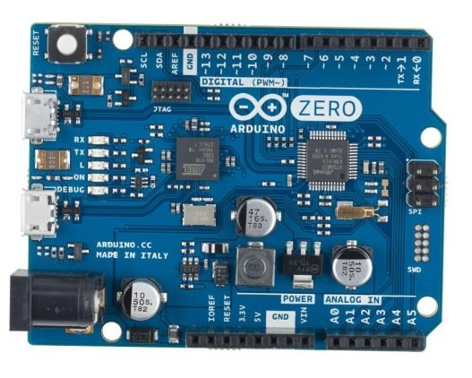
UpSmart PCBA supports OEM & EMS, PCBA for Consumer, open-source development board PCBA, Arduino compatible controller board, consumer electronics PCB assembly, maker education development board, hobbyist electronic controller PCB, USB powered microcontroller board, DIY electronic project kit PCBA, IPC Class 2 consumer PCBA, educational electronics kit assembly, retail consumer electronics PCB manufacturing
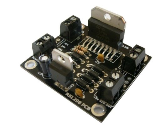
UpSmart PCBA supports OEM & EMS, PCBA for Robotics, dual H-bridge motor driver PCBA, L298N motor controller board assembly, DC motor drive PCBA for robotics, smart car motor driver PCB, industrial robot motion control PCBA, stepper motor driver module assembly, robotics power electronics PCBA, IPC Class 2 robot controller board, embedded motor drive PCB manufacturing, mobile robot motor control PCBA
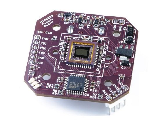
UpSmart PCBA supports OEM & EMS, PCBA for Security, security camera PCB assembly, CMOS sensor module for surveillance, analog CCTV camera PCBA, IP camera motherboard assembly, low light imaging PCBA for security, IPC-A-610 security electronics assembly, surveillance camera board manufacturing, security device PCBA traceability, machine vision camera module PCBA, infrared security camera PCB
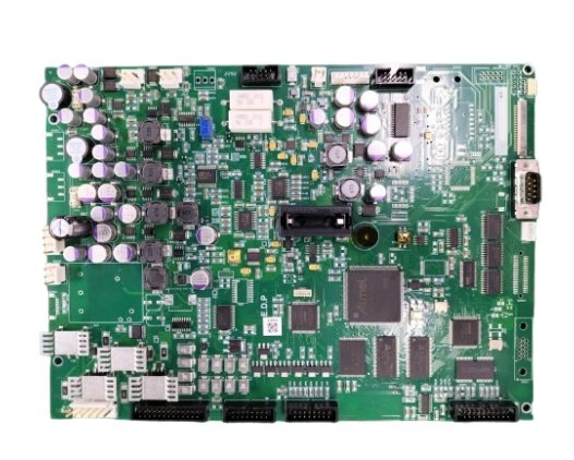
UpSmart PCBA supports OEM & EMS, PCBA for Medical Device, medical device PCBA manufacturing, ISO 13485 certified EMS for medical electronics, ventilator control board assembly service, IPC Class 3 PCBA for medical devices, medical PCBA traceability requirements, high reliability PCBA for respiratory devices, medical electronics contract manufacturing, DFM for medical device PCB assembly, medical grade component sourcing for PCBA, respiratory therapy device PCB assembly
specializing in end-to-end printed circuit board fabrication and full-turnkey PCB assembly services.